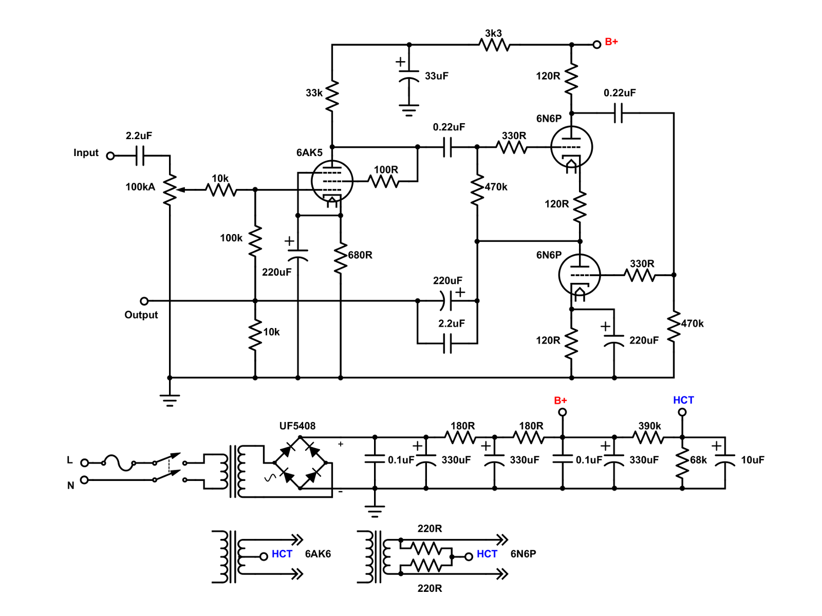
Little Dot Mk II Rebuild
Jan 21, 2021 at 3:43 PM Post #31 of 67
I got my Little Dot Mk II several years ago. After playing around with it for a while, and totally screwing up the PCB with lifted pads and such ('cause I didn't know what I was doing), I put it away on the shelf. In the meantime, I got into building tube guitar amplifiers, then tube hi-fi amps, and recently, OTL headphone amps. Having learned quite a bit about hollow state electronics, I decided to see what I can do with the long neglected Little Dot. Cracking the little guy open, I forgot the horrors that I had inflicted on the PCB. I salvaged the power transformer and whatever components, and traced out the circuit:

LDMKII.png

It's actually a really neat little circuit. The gain switches are variable negative feedback switches, with resistances of 470k, 149.9k, 82.5k, and 59.9k. The EF95 is wired as a triode. In the manual, the output sections were described as having a SRPP topology. Actually, it's a self biasing White cathode follower, which is actually better at driving low impedance loads such as headphones.

I made some modifications to the circuit:

HA-02.png

First, I moved the input coupling capacitor to before the volume potentiometer. A 100k stepped attenuator was swapped in for the cheesy 10k pot. I set the negative feedback resistor to a fixed 100k as I had the switches set to 82.5k, but had wanted just a bit more gain, but not as much as 149.4k. I added a 100 ohm resistor between the screen and the plate to prevent oscillations. I also increased the film bypass capacitor on the output coupling cap (220uF) to 2.2uF from 0.68uF, increased the bypass caps on the power supply to 0.1uF from 0.047uF, and added a virtual center tap to the heaters of the output tubes. The original heater elevation voltage was about 5V, and I upped it to about 28V. I also beefed up the bridge rectifier, using 4 UF5408 diodes.

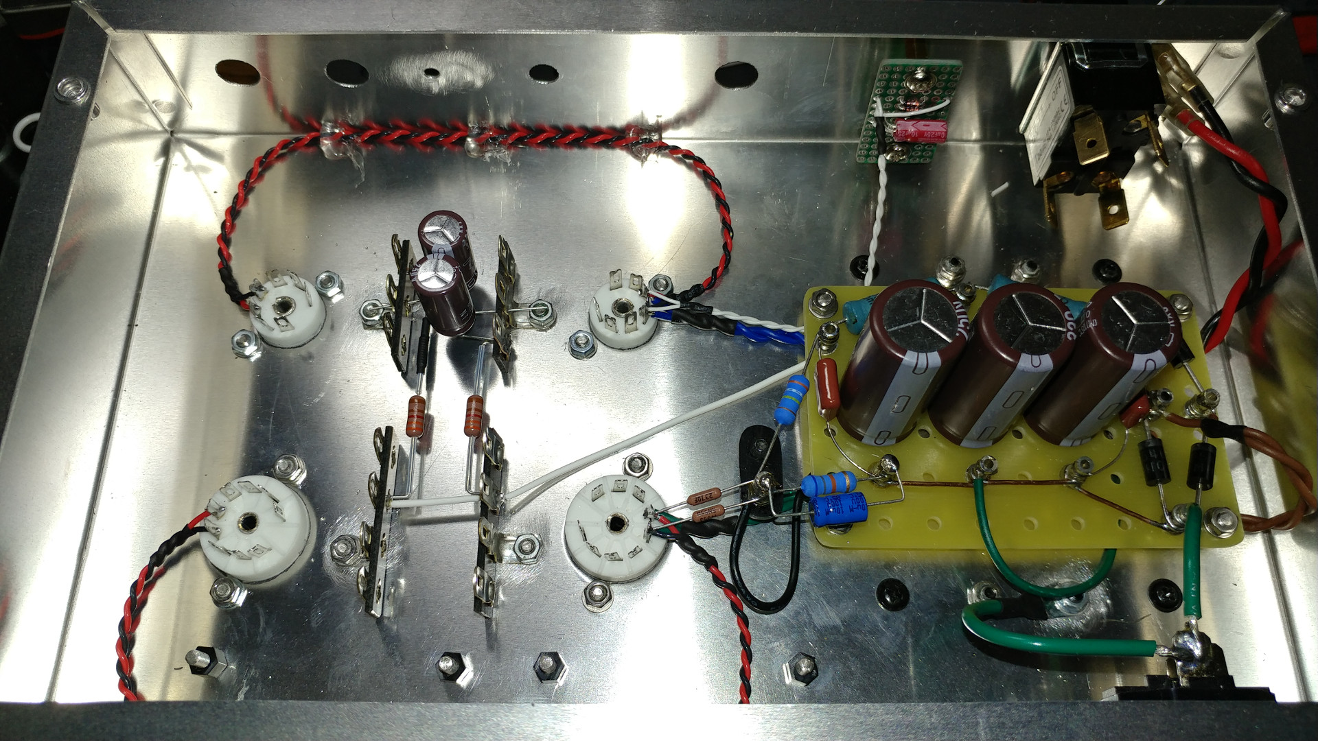
The chassis drilled and painted. The orientation has been changed. It's a Hammond 10" x 6" x 2" aluminum chassis:

01 Chassis.jpg

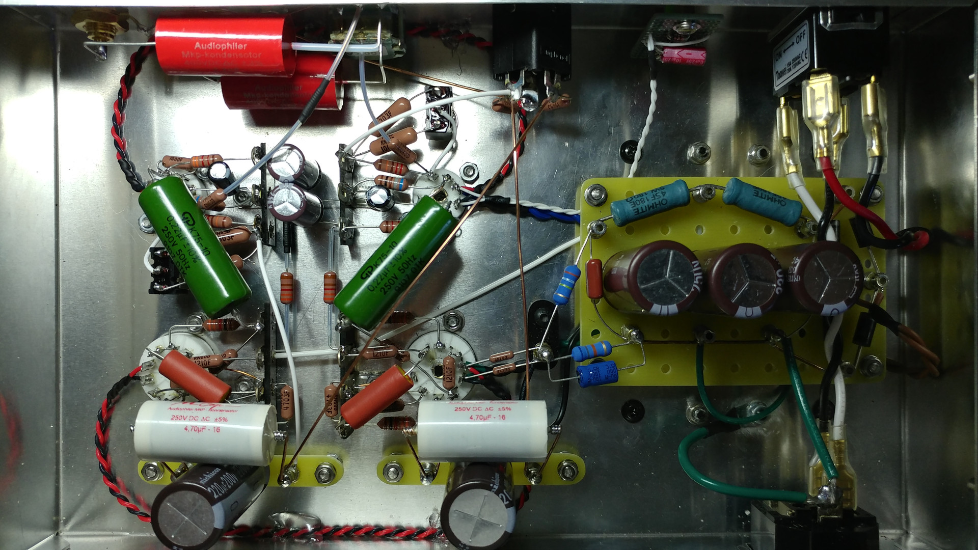
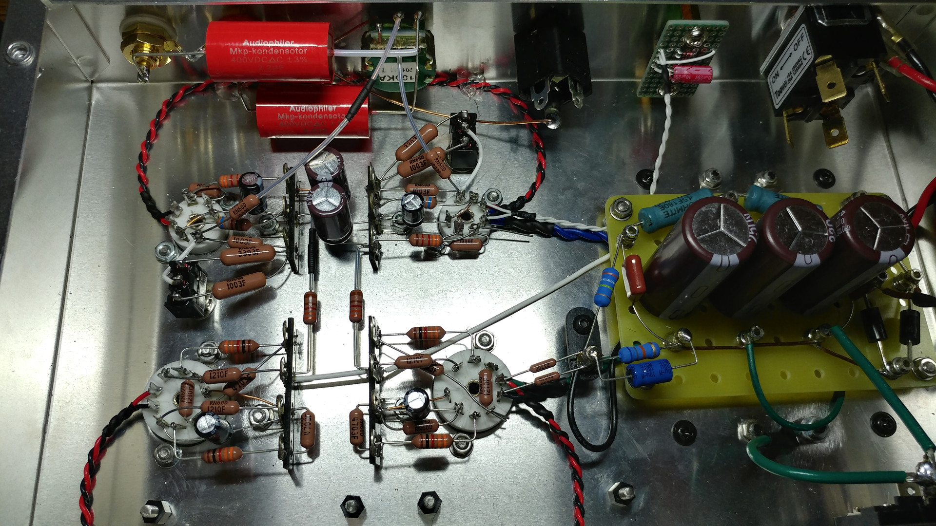
Power supply built on a turret board:

02 Power Supply.jpg

Power supply installed, along with the rest of the power circuit, and the filaments:

03 Filaments.jpg

More pictures to come as I progress on the build.
hi,
great work!...but why do you need that 2.2uf input capacitor?, ...I think there is a little need for it, and can be removed for better sound quality!
:)
 
Jan 22, 2021 at 5:55 PM Post #32 of 67
hi,
great work!...but why do you need that 2.2uf input capacitor?, ...I think there is a little need for it, and can be removed for better sound quality!
:)

I built this for my kid in college. I trust him not to do anything stupid, but not his friends, who may plug who knows what into the input. I remember my college days and all the stupid things I did. It's insurance. :smile_phones:
 
Mar 17, 2021 at 10:19 AM Post #34 of 67
Inside looks even better than original Chinese PCB design, good work, I'm now thinking to upgrade the volume pot on my LD i+ because at very low volume the sound is imbalanced, would you recommend any good VP?
 
Mar 22, 2021 at 7:25 AM Post #36 of 67
hi i have a slight - middle channel imbalance at any volume and some frequencies muffling on the right channel, i checked everythign and it comes for this little dot , but my knowledge is same as yours 5 years ago :) can you tip will which component i should check / replace to eventuallky fix my board too ?

iiuc replacing the pot with a dact stepper one is first approach for channel imbalance right ?
Any idea what else can be done ?
 
Mar 22, 2021 at 7:16 PM Post #37 of 67
hi i have a slight - middle channel imbalance at any volume and some frequencies muffling on the right channel, i checked everythign and it comes for this little dot , but my knowledge is same as yours 5 years ago :) can you tip will which component i should check / replace to eventuallky fix my board too ?

iiuc replacing the pot with a dact stepper one is first approach for channel imbalance right ?
Any idea what else can be done ?
Try swapping tubes between the channels. First do the EF95 and then the 6N6P. Other than the tubes and the volume pot, there shouldn't be anything else in the circuit to cause the imbalance.
 
Mar 23, 2021 at 9:23 PM Post #38 of 67
i tried that and have a lot of tubes to test, maybe the transformator provide somehow different heater voltage to the tubes ?
Anyway i will swap the pot as first approach Thanks
 
Mar 23, 2021 at 9:59 PM Post #39 of 67
i tried that and have a lot of tubes to test, maybe the transformator provide somehow different heater voltage to the tubes ?
Anyway i will swap the pot as first approach Thanks
There are 2 different 6.3V windings in the transformer, but they supply the EF95 and the 6N6P separately, so the left and right channels should get the same voltage.
 
Mar 24, 2021 at 6:39 AM Post #41 of 67
thanks for clarification.
On the little dot mk1 there are 2 resistors (i think) next to the op-amp stage with a small screw for adjustment, any idea if this is only when using a a solid state and if it is related to some channel imbalance fixing too ?

pic : https://cdn.head-fi.org/a/10201118.jpg
The Little Dot 1+ is a totally different animal than the Mk II, and I have no experience with it. I don't fool around with solid state stuff much, so I can't comment on it based on the pictures. Sorry.
 
May 5, 2021 at 1:35 PM Post #42 of 67
@drteming

I have to add an external power supply to my LD2 to feed the C3g heaters that I use instead of 6AK5... those C3g required 390mA each and the transformer in underpowered for that with, as result, only 5,7Vac on the heaters which is bad

one question about the first diagram you posted here, that should represent the LD as from factory, are you sure about the connection between middle of secondary driving 6AK5 and + V ?

F8A00B8F-F7B1-449F-8ADC-7CA3D38AA671.jpeg
 
Last edited:
May 5, 2021 at 4:47 PM Post #43 of 67
@drteming

I have to add an external power supply to my LD2 to feed the C3g heaters that I use instead of 6AK5... those C3g required 390mA each and the transformer in underpowered for that with, as result, only 5,7Vac on the heaters which is bad

one question about the first diagram you posted here, that should represent the LD as from factory, are you sure about the connection between middle of secondary driving 6AK5 and + V ?

F8A00B8F-F7B1-449F-8ADC-7CA3D38AA671.jpeg
Yep. From the factory, the heater center tap for the 6AK5 tubes are elevated above ground. It was only 5V or so iirc. The heater elevation reduces leakage from the heaters to cathode, and reduces hum. The 5 volt was a bit too low. Usually you want about 30V above the heater potential.
 
May 9, 2021 at 12:20 PM Post #44 of 67
question: if with tester I check between one of the EF95 heater contacts, in the tube sockets without tube plugged in, and the ground (housing or external contact RCA or housing screws) ... what should I have? continuity or insulation?
from the first scheme here I should see continuity trought the 5k1 resistor to ground... but I find it insulated, as insulated is the heater of 6N6 :thinking:
if I put the tester between the two heater inputs, in the valve socket, I have regular feedback of existing continuity... so I "see" the coil in the transformer, contat points are right

on the pcb is printed V3.0 in my unit too... I'm wondering if this is another example of chinese joke (strange quality)

if I put the tester between katode and ground I can easly measure 680Ohm (ok, to be precise one is 680 and the other is 677)... so, am I doing something wrong measuring "elevation" connection ?
 
Last edited:
May 9, 2021 at 3:05 PM Post #45 of 67
question: if with tester I check between one of the EF95 heater contacts, in the tube sockets without tube plugged in, and the ground (housing or external contact RCA or housing screws) ... what should I have? continuity or insulation?
from the first scheme here I should see continuity trought the 5k1 resistor to ground... but I find it insulated, as insulated is the heater of 6N6 :thinking:
if I put the tester between the two heater inputs, in the valve socket, I have regular feedback of existing continuity... so I "see" the coil in the transformer, contat points are right

on the pcb is printed V3.0 in my unit too... I'm wondering if this is another example of chinese joke (strange quality)

if I put the tester between katode and ground I can easly measure 680Ohm (ok, to be precise one is 680 and the other is 677)... so, am I doing something wrong measuring "elevation" connection ?
I wonder if the power ground is separate from signal ground. I didn't check on the PCB before I trashed it. The case is anodized, so it's going to be insulated. I found a picture of an unmodified amp (cribbed it from the the original LD MkII thread). I added the legends so you know where to measure.

9443934.jpg
 

Users who are viewing this thread

Back
Top