My DIY electrostatic headphones
Jun 3, 2022 at 7:53 AM Post #3,916 of 4,061
I have bought from ebay or aliexpress few years ago, but not angled and cheap artificial leather. They were not very big either, but covered my whole ear. I guess you won't like them. Otherwise give me a hint, I'll look through my orders.

Edit:
Just out of curiosity I browsed and found these:
https://www.aliexpress.com/item/4001120856185.html?spm=a2g0o.productlist.0.0.240974e50npwqS&algo_pvid=3921c7a0-0285-4dfb-b928-ad26ab13170f&algo_exp_id=3921c7a0-0285-4dfb-b928-ad26ab13170f-53&pdp_ext_f={"sku_id":"10000014548379220"}&pdp_npi=2@dis!USD!!5.94!!!!!@2103143616541212174365180e8329!10000014548379220!sea
With this price they don't look to me a genuine leather, but still.... Otherwise found a lot other sheepskin leather, but not angled.

Thanks, i quess i will have to try nonagled version then, I found with 110x90mm dimmensions.
https://www.aliexpress.com/item/1005003380649489.html?spm=a2g0o.cart.0.0.aad43c00QXLE5W&mp=1
 
Jun 3, 2022 at 3:25 PM Post #3,917 of 4,061
Made some measurements. In the bass region it look like yours Tib8, but in middles and highs nowhere near. Bass is boosted starting from about 200-250, but from there all the rest is pretty flat up to 20kHrz (laptop output, otherwise it goes much higher).
Again :beerchug: many thanks Wachara - look what graphene did at the range 2k-6k (about 10db better) - the orange graph is with softener, the rest are with graphene . I also played with some HPF at about 120 Hrz, 20dB/ decade - made it completely flat bellow 300. Then I tried also the windows EQ (blue line) which made it better looking. Yes - better looking - but not better sounding. May be I got used to the boosted bass, but after that EQ , I did not enjoy it anymore.
Anyway, I think the reason for the boosted bass with the 2 membrane design is the twice lower equivalent volume (Thielle-Small). May be it's time for another build with much smaller active area, to see how it will perform.
Cicle 90mm measurements.jpg
 
Last edited:
Jun 9, 2022 at 8:59 PM Post #3,918 of 4,061
Hi everyone, this is my first post on head-fi, I'm very happy to share my experience of making electrostatic headphone with you, many thanks to chinsettawong for the invitation. I've already posted about making Shangri-la clone headphone on both head-case and the China Headphone Club.
https://www.head-case.org/forums/topic/21643-a-diy-shangri-la-headphone-for-hifi-xmen/
http://www.headphoneclub.com/thread-753621-1-1.html
The Chinese version is more detailed, I wanted to repost it to head-fi, but it seems that new accounts cannot upload pictures though. Anyway, If you have any questions, feel free to ask me. :beerchug:
 
Jun 10, 2022 at 8:30 AM Post #3,920 of 4,061
Made some measurements. In the bass region it look like yours Tib8, but in middles and highs nowhere near. Bass is boosted starting from about 200-250, but from there all the rest is pretty flat up to 20kHrz (laptop output, otherwise it goes much higher).
Again :beerchug: many thanks Wachara - look what graphene did at the range 2k-6k (about 10db better) - the orange graph is with softener, the rest are with graphene . I also played with some HPF at about 120 Hrz, 20dB/ decade - made it completely flat bellow 300. Then I tried also the windows EQ (blue line) which made it better looking. Yes - better looking - but not better sounding. May be I got used to the boosted bass, but after that EQ , I did not enjoy it anymore.
Anyway, I think the reason for the boosted bass with the 2 membrane design is the twice lower equivalent volume (Thielle-Small). May be it's time for another build with much smaller active area, to see how it will perform.
Ikos98,
The whole idea of this two membrane construction is that they help each other in movement and this way they cancel out the distortion which would be there due to single ended drive if we would omit the membrane from the outer side, right?
But the membranes are "far" from each other, which means that this "help" arrives with some delay from the other side.
The question: how big is this delay and how big its effect can be?
  1. If we assume that the pressure wave moves with the speed of sound, then in my case the 4mm distance needs about t= s/v = 0.004m / 300m/s = 13us; f = 1/t => 75khz - so that is likely not an issue...
  2. On the other hand if we calculate with the speed of the gas molecules (which were hit by one of the membranes, so their speed has changed) and travel to the other side then the picture is pretty different: vrms = sqrt(3*R*T/M) = sqrt(3*8.314*293/30) = 15.6m/s => f = 3900Hz sqrt(3*8.314*293/0.03) = 493m/s => f = 123kHz
    (also they are likely not travelling along a straight line, which further lowers this frequency)
So my idea is that this bass boost is due to this second effect: on low frequencies the membranes are really able to help each other!
This theory could be checked by reducing the distance of membranes - if the boosted region extends to higher frequencies, then I was right. :)
(Also, more "open" and thinner middle stator (like a mesh) can help this boosting effect extend further to highs.)
Unfortunately to reach my limits (about 14kHz,) the distance should be reduced to about 1mm, which is not really possible with FRV stators, and surely much smaller driver diameter will be needed for the smaller airgaps too.

Of course this speculation can be totally false, so I need to repeat measurements when I find time, to decide.


In any case if the "help" arrives with a delay which opposing the phase, then that is not help, but the opposite, so even with the first assumption may have some effect...

EDIT: I realized that I used wrong mass unit to calculate the speed in second case, so this post is mostly not relevant anymore. :frowning2:
 
Last edited:
Jun 10, 2022 at 6:02 PM Post #3,921 of 4,061
Yes, one of the things is the "mutual help" of the 2 membranes, the other is to reduce the capacitance - with my setup I have about 50pF (40 cable and 10 from the phones) as a load to the amp. On 22 kHrz this gives me around 150kOhm impedance, so the max current is 220RMS/150k ~= 1.5mA, while most of the amps I heard of are running at 8-10mA. In fact this increases the efficiency - 0.35W against 2W (not even mentioning the efficiency of the amp itself).
About the delay - I would use some simpler math. The wave length of 30kHrz is 11mm much longer than 0.8+0.8+1.6 = 3.2mm distance between the membranes. In other words, these 2 membranes act as single one up to some 50's kHrz before half wave length kicks in. This cannot be an issue for the bass boost, since the wavelength there is few meters.
I still can't explain where this bass boost comes from - I hear it in all my models, especially after I doubled my biases. I have some idea, but need to experiment more, to figure it out. In any case I like it, it' not irritating, it's deep, but tight and once you get used to it, it's very enjoyable. I have one pair dynamic Klipsh, which are also very bassy and I have heard also those (some DJ produced - can't remember the name, they were quite famous 5-10 years back) - bass is way too much and boomy.
 
Jun 27, 2022 at 10:44 AM Post #3,923 of 4,061
hi all
what bias boards you use?
I tried different ones like QS30-1.IN-14
but I think there is something better

what transformers you use?
I tried regular power transformers like 220v -> 3v
transformation ratio was like ~ 70

maybe someone knows where to find more?
150-300?
I suspect that these must be power transformer
like 380v -> 1v or something like that
but i dont know where to get it

What sort of bias voltage do you wish to achieve?
 
Jun 27, 2022 at 8:08 PM Post #3,925 of 4,061
Out of curiosity, has anyone tried to go for a relatively loose tension on the mylar? Im thinking about using water tension to stretch the mylar flat and use fairly thick spacers (1-2mm) to avoid stator slap.

Obviously this would require very high bias voltage, but so long as I manage to keep things 3KV and below, it should be pretty easy.

I just want to get all of your thoughts before I waste time and material going down this rabbit hole
 
Jun 29, 2022 at 1:38 PM Post #3,928 of 4,061
Out of curiosity, has anyone tried to go for a relatively loose tension on the mylar? Im thinking about using water tension to stretch the mylar flat and use fairly thick spacers (1-2mm) to avoid stator slap.

Obviously this would require very high bias voltage, but so long as I manage to keep things 3KV and below, it should be pretty easy.

I just want to get all of your thoughts before I waste time and material going down this rabbit hole
A friend of mine tried a similar idea, directly using low tension copper foil as estats diaphragm, using 2mm spacer、2000V+ bias and a step up transformer to drive it like an electrostatic speaker, it just works, but soon, he switched to stax pro bias driver. :)

Similar design electrostatic headphone is already commercially available. For e.g., Sonoma M1 and its subsequent models Aperio and Bravora,these estats use low tension metal-coated interlayer film as the diaphragm + flexible mesh stators, and their bias voltages are set at 1350VDC (M1 and Bravora) and 1800VDC (Aperio) respectively.
 
Jun 29, 2022 at 7:25 PM Post #3,929 of 4,061
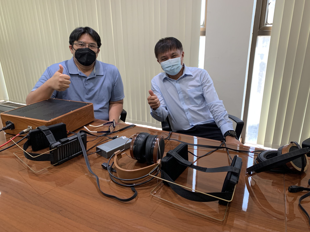
All of them are great sounding!

Correction! Incredible sounding!!

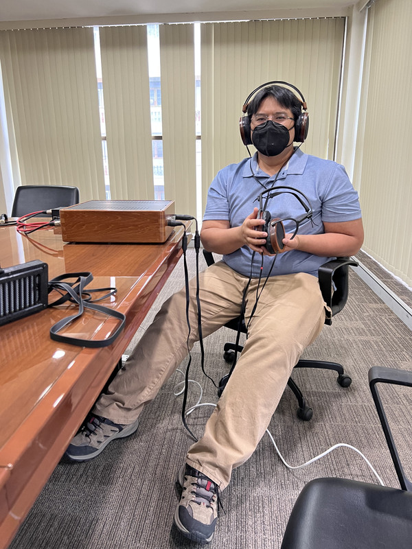
Such a pleasure to listen to these fine creations. Thank to P Wachara for taking the time out of his busy schedule to chat with us. Note that the meeting took place in his very own conference room.
 
Last edited:

Users who are viewing this thread

Back
Top