The
bypass/decoupling caps are not in the audio signal path and should have no influence on the final output sound, well...at least if op-amps are not oscillating and PCB and it's ground plane are well designed and also the power supply is free of noise & ripple (only a scope will tell us that, not our own ears!). The decoupling caps are used so the op-amps to receive a less-noisier and ripple-free power and not to improve the audio performance in any ways, well...unless the power supply is really crappy and the capacitors used for decoupling could do improvements indeed (though, usually the design needs to get changed if PSU's ripple is too high). So all it matters for the decoupling would be the lowest ESR possible and the best ripple rejection capacitors and a tantalum cap in parallel with a ceramic would make a very good example for decoupling a high-speed op-amp. Tantalums have lower ESR than regular electrolytics and much better ripple rejection combined with a higher in-rush current.
A really good reading about decoupling here:
http://www.analog.com/media/en/training-seminars/tutorials/MT-101.pdf.
Some good stuff to read about tantalums here:
- https://www.quora.com/What-are-the-differences-between-electrolytic-tantalum-and-ceramic-capacitors
- https://www.illinoiscapacitor.com/pdf/Papers/comparison_surface_mount_aluminum.pdf (last page)
- https://www.techwalla.com/articles/the-difference-between-electrolytic-tantalum-capacitors
- https://www.engineersedge.com/instrumentation/tantalum_capacitors.htm
Usually, if an op-amp is not getting stabilised with a regular 10uF electrolytic or with a 1uF tantalum (with a 0.01-0.1 non-polarised cap in parallel), then the design or the op-amp itself needs to get changed. Adding 100uF or more for decoupling could help when length of the PCB power rails from PSU till op-amps are huge and routed across many active electronic devices (DC-DC buck converters, ARM chips etc.), but adding very big caps for decoupling op-amps it's just not a best practice and if design and implementation are good enough then these big decoupling caps should not get the sound changed in any way. However, a simple oscilloscope should prove this with ease, so feel free to give it a try.
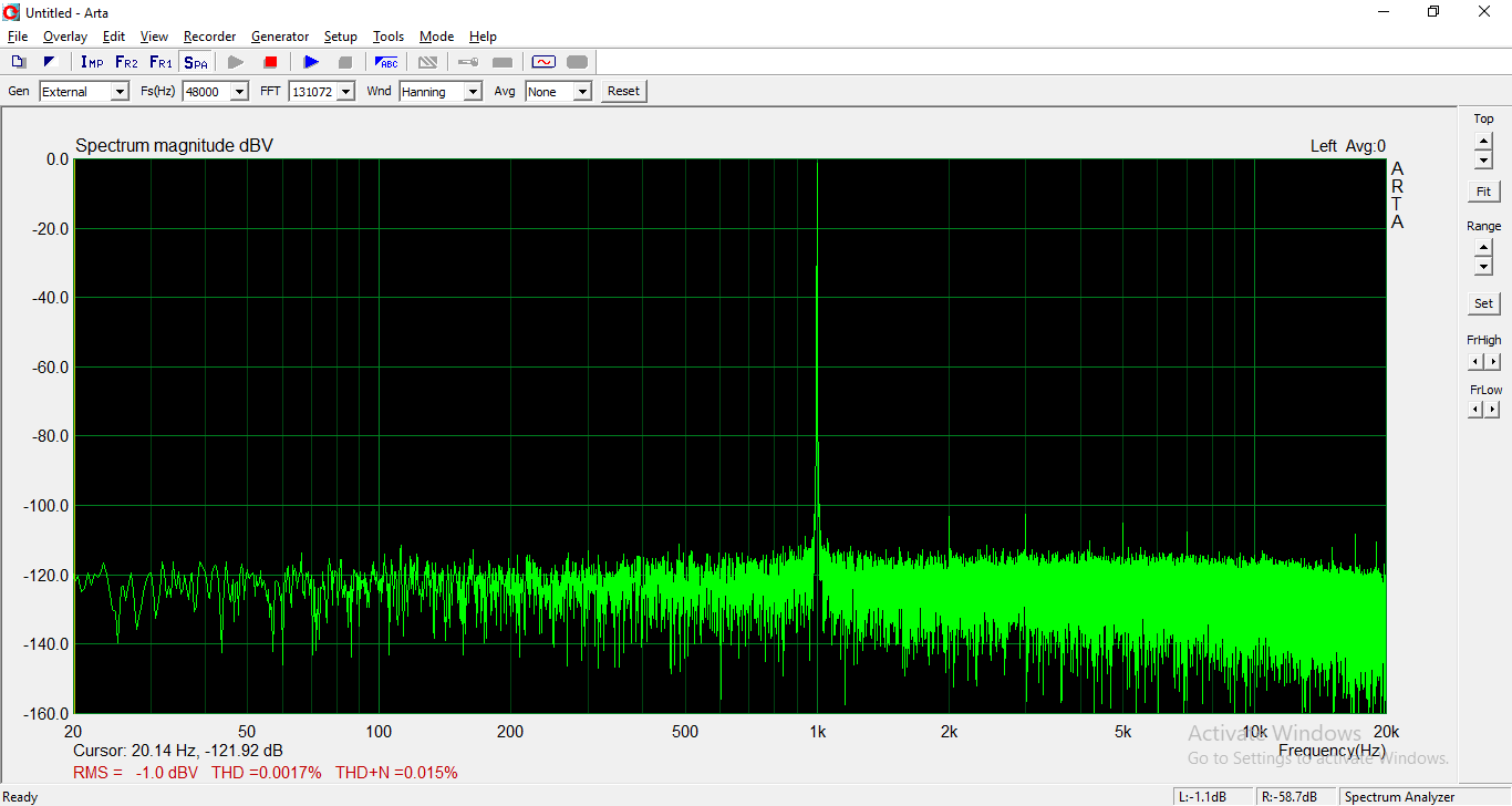
P.S.: I've seen this with my scope and it has been proved for several times in audiophile and audio-electronics websites that the
power supply noise is getting injected into the final output sound and this is a
proven truth, so I'm aware that a noise-free PSU is the key of a very clean output sound, but
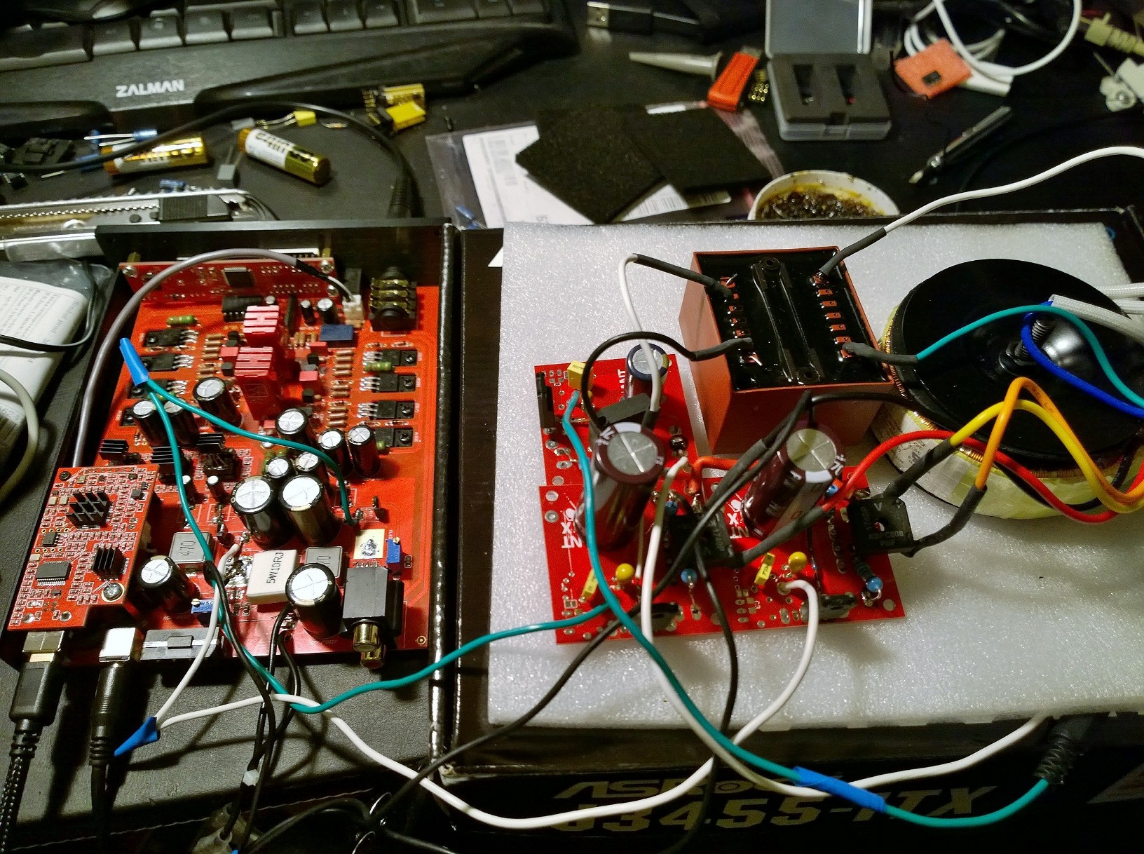
increasing op-amp decoupling caps will not resolve PSU noise, nor design flaws of your DAC or amplifier! For example, this is what I did when I had noise, hum and high visible ripple shown on my scope on one of the DACs I own:
https://www.head-fi.org/threads/asu...-dac-cebit-2011.542563/page-229#post-13130247. So yes, shielding the transformer, resolving PCB and ground plane issues, upgrading to better LDOs (with lower-noise and higher ripple rejection), increasing filtering capacity of the power rails (+5V and +/12V) of the PSU and adding a dedicated +5V PSU only for the DAC chips did resolved most of the issues with my equipment. Also, using big-enough and very good quality electrolytic caps (Nichicon, Elna etc.) in the power supply it is indeed a very good way to decrease noise and ripple on the power rails as long as the PCB traces and rectifying diodes can sustain the higher load when powering up the device, otherwise more modifications need to be done.


![IMG_20190528_225418[1887].jpg](https://cdn.head-fi.org/a/10307231.jpg)


")


