Input Ground Isolation on AC Dual Voltage Power Supply
Apr 30, 2010 at 9:49 AM Thread Starter Post #1 of 10

earfonia

Headphoneus Supremus
Joined
Apr 13, 2010
Posts
2,490
Likes
4,728
Location
Singapore
I've searched google and DIY section here a few hours, but couldn't find the solution I'm looking for.

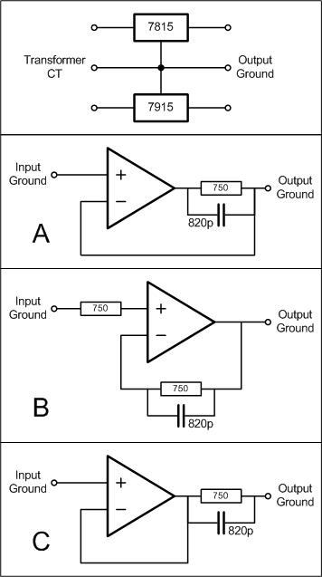
I would like to build a headphones amplifier, with AC power, using dual voltage power supply, with 78xx/79xx or 317/337 combo (or other regulators). Will use Transformer with center tap.

My question is, what is 'the best simple way' to connect the input ground (from source) with the power supply output ground, that provide isolation between the input and output ground?

I would like to have some isolation between input ground and output ground like what I see in PPA project, but since I'm using dual voltage power supply with Transformer CT as the ground, I would like to save cost from building another ground channel amplifier with buffers.

I'm looking for some advice. I've thought a few ways, not sure if any of them will works well. Please advise which way from the picture below, option A, B, and C, do you think is the better way to connect input ground to the output ground. Or if you have a better way, I really appreciate if you could share it with me.
Tx!
smily_headphones1.gif


Ground.png
 
Apr 30, 2010 at 10:38 AM Post #2 of 10
Lots of things to cover here.

1) Transformer with dual secondaries vs single-supply.
2) Passive vs Active ground and Real vs Virtual (derived) ground reference.
3) "Audiophile" ideas to consider.

Lets start with the first 2. If you're really going for "simplest" solution, you would get a center-tapped or dual output transformer and use that as a a ground with a capacitor bank across each rail. If you would like to regulate it, you would go with the first photo. The other images go with a buffered ground channel. This goes with the assumption that the passive ground must be improved upon and that there is "benefit" to "improving" the ground scheme of the circuit. There is certainly some dispute about this, but lets go above that... there are different ways to do this. Personally, I have not learned enough of any of those three circuits to discuss them, so I will welcome the knowledge of others on this topic. Good luck with this discussion, I look forward to reading it!
 
Apr 30, 2010 at 12:51 PM Post #3 of 10
If your input ground is bad, you have bigger problems. You should fix that at the source.

Maybe you mean mains ground, in that case use a ground loop breaker .

I've never had a problem with the center tap of the transformer connecting to audio ground using star grounding.
 
Apr 30, 2010 at 2:53 PM Post #4 of 10
Quote:

Originally Posted by regal /img/forum/go_quote.gif
If your input ground is bad, you have bigger problems. You should fix that at the source.

Maybe you mean mains ground, in that case use a ground loop breaker .

I've never had a problem with the center tap of the transformer connecting to audio ground using star grounding.


Not mains ground, but the source / player ground.

I know we can just connect the player ground with the amplifier ground, I use to do that as well. But in the PPA project, isolating low current source ground with the busy high current amplifier ground also make sense, and it might improve the sound quality. That's what I want to try. But I don't know how to do it when using AC power supply with dual voltage. Using single voltage supply, virtual ground is a must to split the voltage supply, and that makes isolating input and output ground easier. But in dual voltage supply, the amplifier ground is already provided by transformer CT, so isolating the input ground becoming tricky.
confused.gif


The question is:
Is there any difference connecting the player ground directly to the transformer center tap (output ground), compared with isolating the player ground with the output ground?

If isolation is better, how to do it on dual voltage power supply?
 
Apr 30, 2010 at 3:40 PM Post #5 of 10
Quote:

Originally Posted by earfonia /img/forum/go_quote.gif
If isolation is better, how to do it on dual voltage power supply?


You would achieve full ground isolation with signal transformers.

It is as close to ground loop proof as you will find, and generally awesome.

As far as whether this is overkill or not, you bet it is! Something nice about it is that the transformers could very easily be built as another project into their own little box with short interconnects from them to the amp. This would allow them to be used with several projects, and the resale on unwanted old amps to be in line with every other DIY of the same thing. Despite the fact that it is better to have input transformers it is difficult to find someone who will pay the extra $100 on the used market. Those who do get the rewards from that, but eeh. Reality just sucks.

Edited:
with a little planning (like 2 minutes worth) and maybe 1 extra switch the transformers would also take SE or balanced inputs, and output SE or balanced outputs!
 
Apr 30, 2010 at 10:32 PM Post #6 of 10
there's no real reason to want "gnd-gnd isolation" if you can connect them with much lower impedance with proper star gnd layout

you should want to keep Class AB nonlinear ps return currents flowing in the +/- ps rails from inductively coupling to any signal path wiring and if the ps/gnd return paths diverge you want to prevent nonlinear voltage drops from the return current from showing in the signal path gnd

doing a great job at this does not require a "3-channel" amp as is popular here - just good layout of the ps/gnd and input&feedback reference points in a dual supply amp - carefully thinking about the current paths and keeping star gnding principles in mind

EI split bobbin pwr xmfr will have greater line isolation than toroidal xfmr - but does leak more magnetic field - needing more space or iron shield
the greater line isolation from lower pri-sec interwinding capacitance results in lower AC gnd loop current in the system so I prefer EI ps xfmr

an additional step up in "gnd quality" would be to go to "dual monoblocks" - 2x dual ps, isolated from each other, one supplying each channel is going to be cheaper than quality audio frequency signal i/o transformers

using a 4-pin "balanced" headphone connector would also reduce measurable R/L channel crosstalk in the standard TRS connectors that put both driver's return current through the common "gnd" contact resistance of ~10 milliOhm - “3-channel” amps don't fix this problem

dual mono, dual ps and 4-pin headphone connectors should closely approach full balanced i/o performance even with single ended amp circuits with good star gnd layout

this shows star gnd schematic depiction - but shows "active gnd" ps rather than my perferred CT "passive" dual ps:
star.jpg
 
Apr 30, 2010 at 11:07 PM Post #7 of 10
The simplest solution is to separate the signal ground (use isolation at the input jacks) and the headphone ground. Connect the ground of the headphone jack back to the power supply with a separate wire. Some would call this a "star" ground if the power supply is in the same chassis as the amp.
 
May 4, 2010 at 1:25 AM Post #9 of 10
I'd rather say there's no reasonable problem requiring input/output gnd isolation - when you properly apply star gnd principles to keep output gnd ps return current from creating "contaminating" V drop in the signal/feedback/driver star gnd point

as a practical matter the star gnd "point" could be a signal gnd plane with the ps gnd return path separated and only joined to it at the output trs connector gnd pin


certainly a differential input/balanced receiver is useful when you have to bridge different branch circuits, fighting large power line gnd loop currents as in pro applications - but not for a desktop system with single ended source and amp plugged into the same line power socket
 
May 4, 2010 at 5:55 AM Post #10 of 10
Quote:

Originally Posted by jcx /img/forum/go_quote.gif
I'd rather say there's no reasonable problem requiring input/output gnd isolation - when you properly apply star gnd principles to keep output gnd ps return current from creating "contaminating" V drop in the signal/feedback/driver star gnd point

as a practical matter the star gnd "point" could be a signal gnd plane with the ps gnd return path separated and only joined to it at the output trs connector gnd pin


Thanks for the tips!
smily_headphones1.gif
 

Users who are viewing this thread

Back
Top