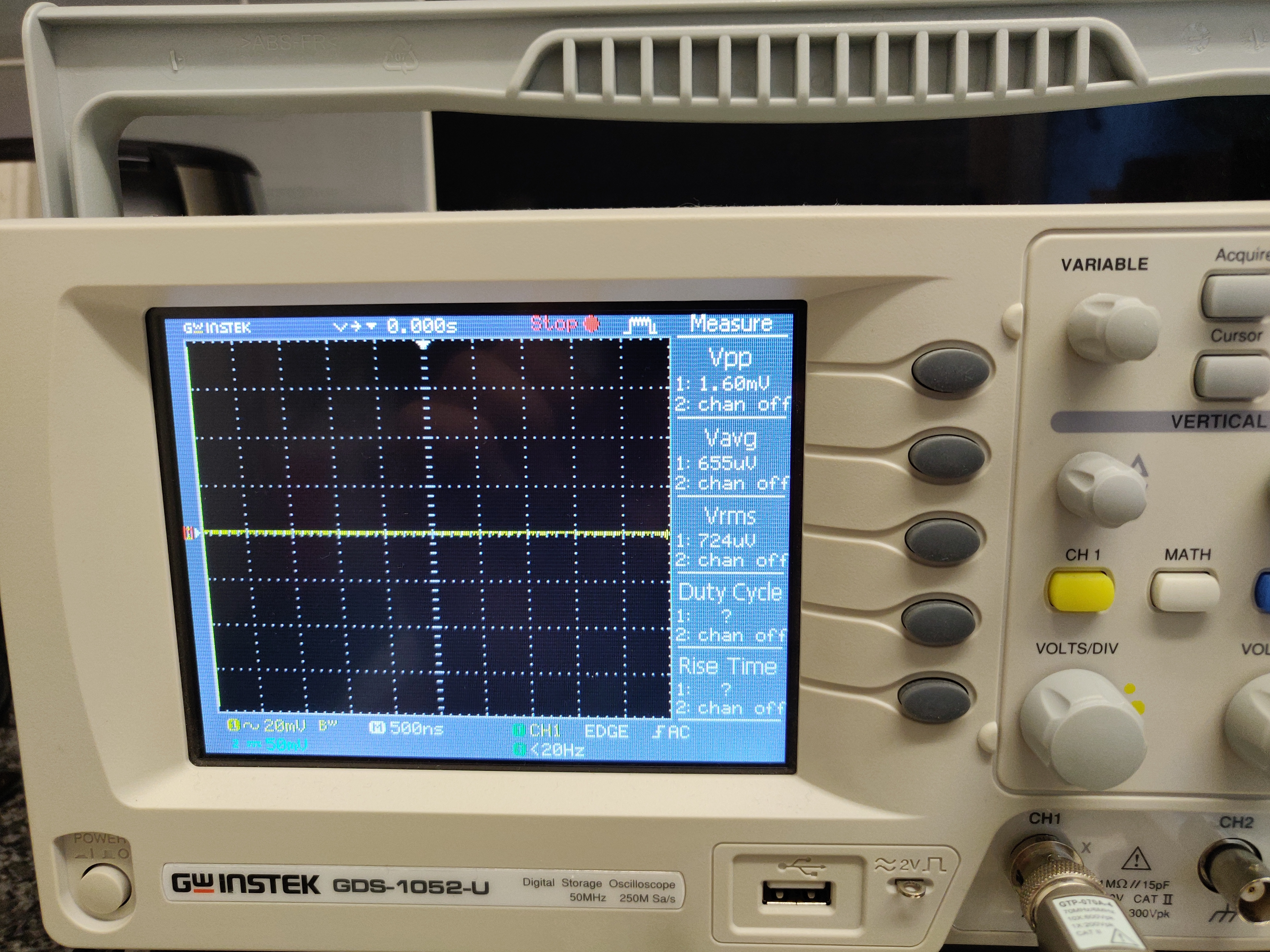
Might be some dumb questions as I'm very new to electronics, but just wanted to make sure:
Would the line out (acting as a preamp) contain the tube colored sound? Yes, as seen in the schematic, both the headphones and line out jacks are connected to the output of the nutube.Would the device be able to output sound to the headphone jack and the line out jack at the same time? Probably, since both hp and line out are always connected to each other. What probably happens is a lower volume output for each since the same signal is being shared.
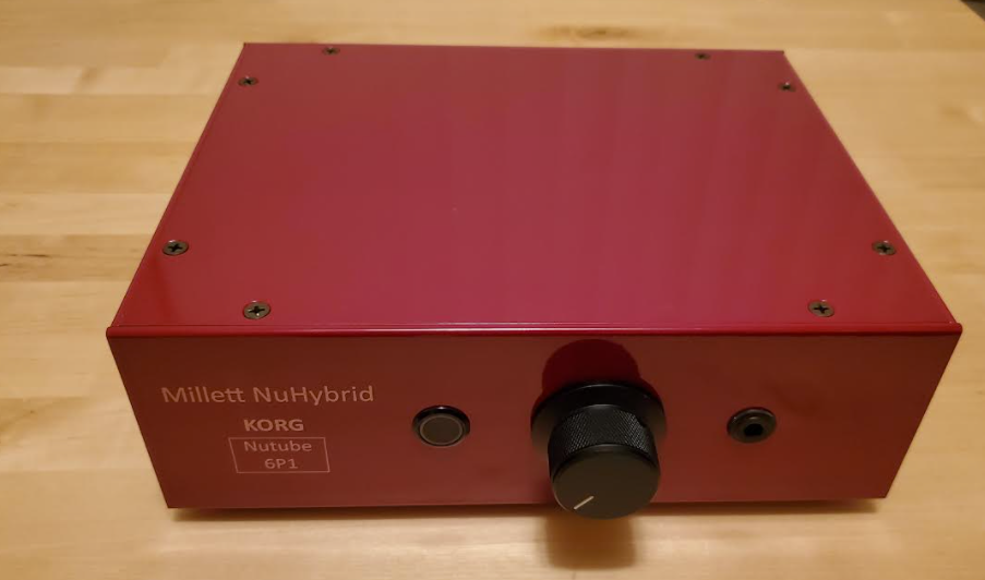
My use case is that I want to use this device to color the sound and provide an easy static way to bridge my dac to both my headphones and my speakers - as I often switch between them.
I believe the headphone jack in the BOM is a switched type, so it disconnects the line out when headphones are in. You'd need to change to an unswitched type to have both outputting at the same time.
Could someone please assist with off-PCB wiring for the volume pot?

Which pad goes to each of the pot pins:
- Input Left
- Input Right
- Input Gnd
- Output Left
- Output Right
- Output Gnd
I am in the final stages of wiring the audio signals to the off-PCB RCA inputs, volume pot and headphone jack. I believe I figured out the headphone jack and RCAs, and only got the volume pot left to be wired...
Thanks!
Did you get one of the recommended pots that fits the board? If so, just see where it fits up on board and connect the same points with wires off board.
If not, I'm going to take a crack at this.
I only have my NuHybrid and build pictures to look at and follow the traces, and the spec sheets I'm finding don't tell me the pinouts. Given how pots work though, I think it would be pretty hard to screw something up badly. Use this advice at your own risk.
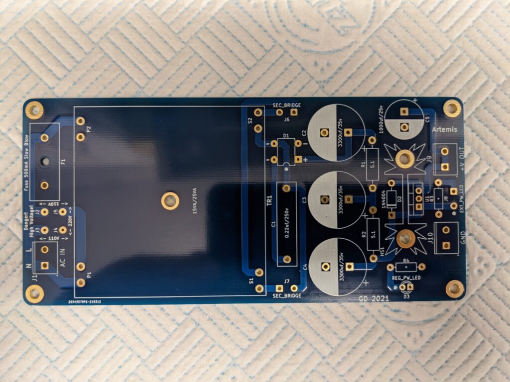
The 6 holes in the middle are bridged by being next to each other, so each pair of those is the same connection.
Similarly, the upper 3 and lower 3 are bridged as pairs as well, so each upper and lower hole is the same connection.
The pots designed to go with this board are stacked per channel (L/R), so pick 1 set on your pot for the inner 6 holes and 1 set for the outer 6. Having them backward would switch your speakers at worst. The board is designed for using 2 different size pots, which is why there's 2 sets of holes.
I don't think pots care about direction, so as long as you get the grounding right, flipping in and out shouldn't change anything. You can check the grounding holes with a multimeter by checking a pot hole to another known ground hole.
The ones toward the inside of the board (left) are all grounds. They're all connected, so it doesn't matter which 2 holes you connect to the pot grounds. I connected my pot case to one of those holes too, so I'm pretty sure on them being grounds.
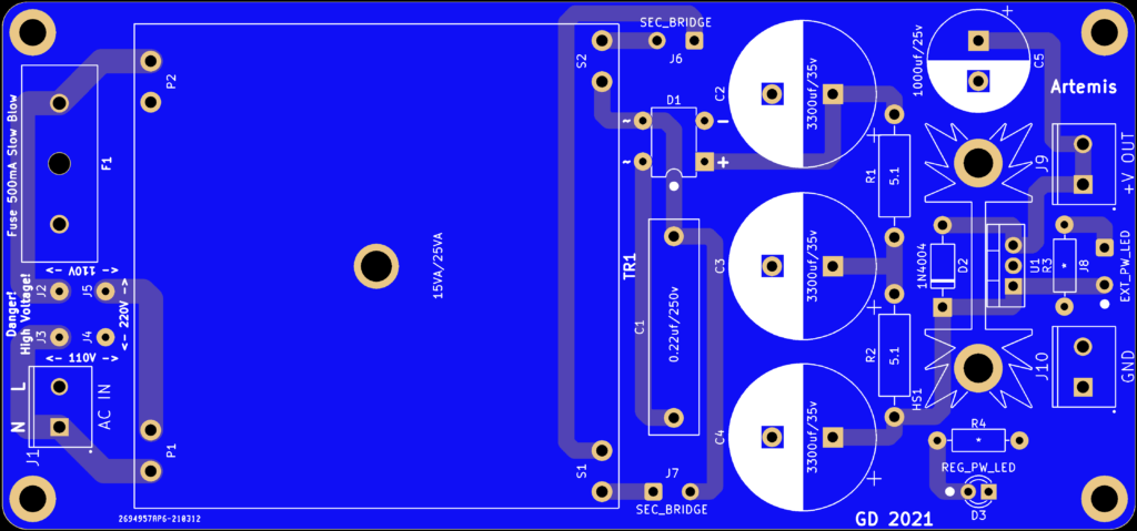
The ones in the middle are the outputs. You can see the traces on the bottom of the board go from the middle holes to C20 and C21. The inner pair goes to C20, so they're right, and the outer pair goes to C21,making them left.
The ones toward the outside of the board (right) are the inputs. You can see the traces on the top of the board coming from the line in. The inner pair is right, and the outer pair is left.
So for mapping, the holes in your picture go:
123
145
145
123
Input Left = 3
Input Right = 5
Input Gnd = 1
Output Left = 2
Output Right = 4
Output Gnd =1
1. 10uF caps: should I go for Nichicon FG (Fine Gold) 50V or Elma Silmic RFS 35V? Price difference is approx. 10 cents/cap, so price difference is NOT a factor.
2. C3 & C6 caps: I read couple posts recommending 1000uF instead of the "stock" 470uF for better bass response. So, in order to fit the PCB (due to case I am going to use, I cannot use parts under the PCB) - I can either use the Nichicon FG 470uF or Nichicon FW 1000uF. Opinions?
I'm one of those guys who asked the same questions and spent way too much time choosing caps. I probably wouldn't have noticed the difference from the BOM caps, but it was fun to learn and make mine unique.
1. I went with Elna's simply for the marketing. I'm sure it's not practically different. I squeezed the fatter 50V ones in there, but it was rough. I bought a set of 35V just in case they didn't fit. Also, just to be different, I undermounted WIMA film caps for C13 and C14 since they were in the signal path, and 10uf films were available in a manageable size. It was really hard to mount them since the leads were so short, but I made it. That whole cluster was really a chore with the size changes I made.
2. I liked the look of the giant Elna caps on the board, so why not. I did have to buy a deeper case to undermount the film caps between them. In theory, a signal cap will pass lower frequencies if it has higher capacity. Capacitors block flow when they fill up, so having more capacitance will let a longer low frequency pass better. I don't think I actually ran the calc, and just went with 1000uF like a couple others. I'd stick with the audio marketed FG caps (or other audio caps) simply for the heck of it. I asked Pete about it when buying the PCB, and he doesn't believe there's a discernable difference between audio and power grade caps, and even that the power grade caps are better since they often have better specs on paper. I know their life ratings were often higher at least. He also told me something about how the signal technically back flows through all the caps and not just the signal path caps, but that was beyond me. On the capacitance, Pete said there would be no difference with my HD650s, but lower impedance like 32ohm headphones would get a slightly increase in bass response


 Any drop-in alternatives?
")
