n_maher
Resistorous Conflagorous
- Joined
- Nov 20, 2004
- Posts
- 8,411
- Likes
- 35
As promised, updated pictures...
Pete is reviewing the final schematic along with the last few questions that I had. I've also managed to dial out the last bit of noise on the inputs. I've got a temporary fix in place and will be adding a permanent solution at some point that will involve a ground lift switch on the inputs. Bottom line, with it in place I'm more likely to hear the fridge running two rooms away through a closed door than I am to hear noise in the background of the amp. :dance:
the amp guts
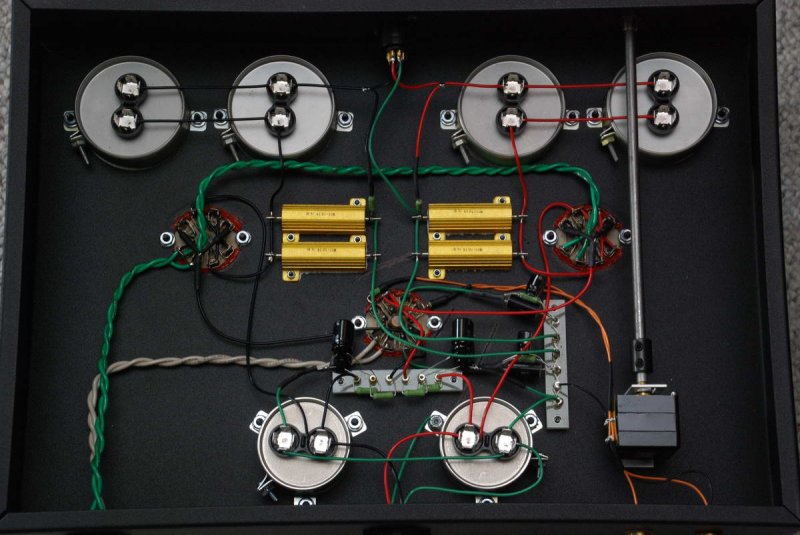
amp top panel

ps guts
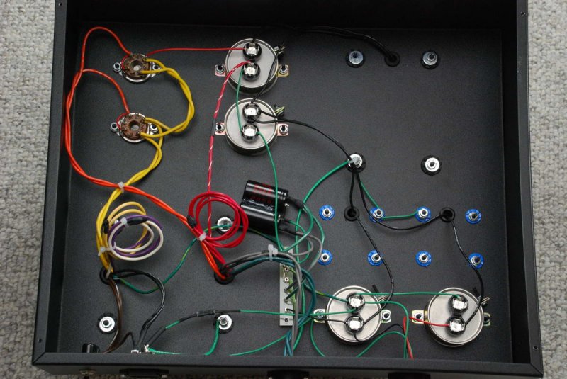
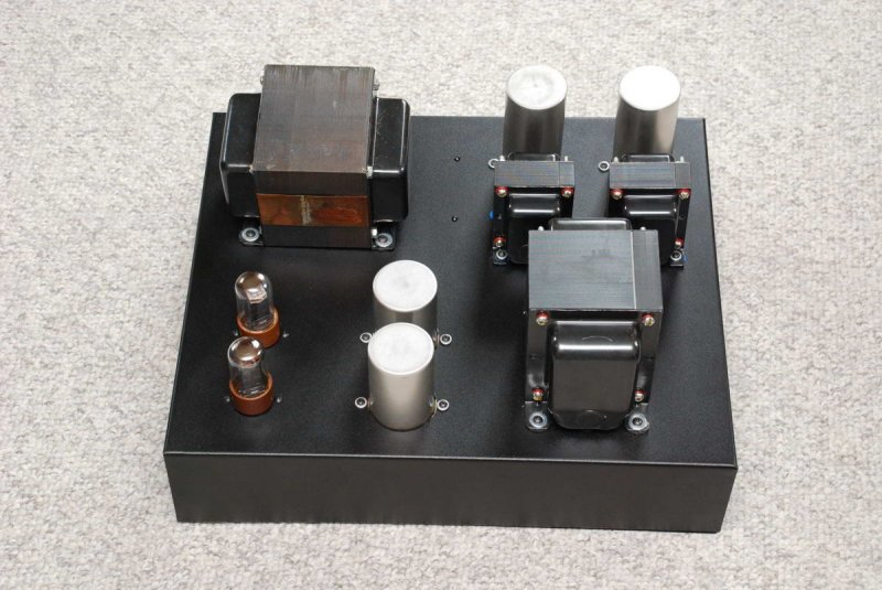
ps top
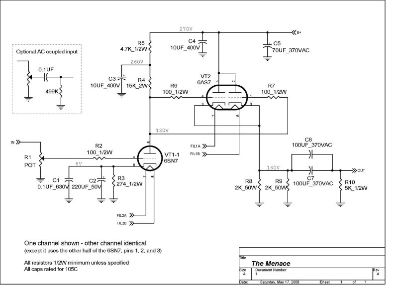
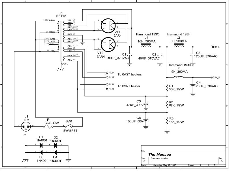
I expect to have the schematic in the next couple of days and I'll post it up as soon as I do.
Listening again tonight, but with different tubes. 5U4GB's/RCA 6SN7/Cetron 5998s - sounds outstanding good to me.
Pete is reviewing the final schematic along with the last few questions that I had. I've also managed to dial out the last bit of noise on the inputs. I've got a temporary fix in place and will be adding a permanent solution at some point that will involve a ground lift switch on the inputs. Bottom line, with it in place I'm more likely to hear the fridge running two rooms away through a closed door than I am to hear noise in the background of the amp. :dance:
the amp guts
amp top panel
ps guts
ps top
I expect to have the schematic in the next couple of days and I'll post it up as soon as I do.
Listening again tonight, but with different tubes. 5U4GB's/RCA 6SN7/Cetron 5998s - sounds outstanding good to me.