Germanium's Sound blaster ZXR mod thread
Mar 3, 2014 at 12:01 PM Post #16 of 272
Source for affordable caps:

ERSE PEx 12uF 250V: http://www.erseaudio.com/Products/PEx250v/12uF-250-volt-Metallized-Polyester-Mylar-Film-Capacitor ($2.97/unit = $17.82 (For 5.1))
ERSE PulseX 12uF 250V: http://www.erseaudio.com/Products/PulseX250v/MPX25-03-12-00   ($4.57/unit = $27.42 (For 5.1))

The other good thing about ERSE Audio is the shipping rates in the US are very low, my cost was two dollars and some change to have 6 capacitors sent to my house.


That sounds great!!!
 
Mar 3, 2014 at 12:46 PM Post #17 of 272
I thought you might like your own picture of the mod in the mod thread, lol.
 
I enhanced it so you can see more detail at the traces and solder points on the PCB.


Mar 6, 2014 at 8:20 PM Post #18 of 272
People will probably mention about the long leads of the bypass capacitors I'm using & some people might even get rather bent out of shape about that issue. I have not had any excess noise issues & cards that I have modified in the past in same way have measured at least as well as stock if not even better noise wise with distortion within reasonable expected deviation one would expect from a stock card  with an even cleaner profile as in fewer spurae that go above the base noise profile.
 
I believe the reason for this is that these metalized film caps are significantly high quality with a much higher resonance frequency & much lower ESR over a broad frequency range thus any noise picked up by the longer leads is countered by the improved ability to shunt that noise to ground. Even when you consider the long leads the overall performance is still far above what an electrolytic can offer. All the caps I used are on the power supply  side & not used for coupling & as such will not add noise to the signal path & actually will probably offer better performance in reducing noise than the short lead electrolytic would be able to offer.
 
The other aspect is that these caps offer better audio performance when used in the power supply as the power supply in transistor gear is typically in the direct signal path so you not only get better RF noise rejection but better offer better audio performance from the amplifier as you can use sufficiently large caps to assist the lower grade electrolytic's in all but the lowest audio frequencies.
 
Mar 7, 2014 at 12:01 PM Post #19 of 272
Look at what showed up in the mail today
very_evil_smiley.gif


Mar 7, 2014 at 8:25 PM Post #20 of 272
Mar 8, 2014 at 2:59 AM Post #21 of 272
Germanium, if you aren't using the headphone amp section of the card at all, do you need to worry with the green boxed caps?
 
Mar 8, 2014 at 6:30 AM Post #22 of 272
  Germanium, if you aren't using the headphone amp section of the card at all, do you need to worry with the green boxed caps?

The green box caps supply power to the opamps as well so yes bypass them with metalized films you have.
 
Mar 11, 2014 at 5:30 AM Post #23 of 272
I should be doing this mod either today or tomorrow.  Out of curiosity, what did yall use to short each cap with?  I figure just cut lead ends to size off some spare resistors and solder each end.  I do have a conductive ink pen (you mask off the path between the two points with tape and draw across it), but I really prefer hard connections.
 
Mar 11, 2014 at 2:51 PM Post #24 of 272
I should be doing this mod either today or tomorrow.  Out of curiosity, what did yall use to short each cap with?  I figure just cut lead ends to size off some spare resistors and solder each end.  I do have a conductive ink pen (you mask off the path between the two points with tape and draw across it), but I really prefer hard connections.


I used bare copper 30 gage wire & soldered them in place with soldering iron & lead free solder.
 
Mar 11, 2014 at 5:31 PM Post #25 of 272
I'll have pictures up by tonight (10PM EST) of the mod done in detail.
 
Mar 11, 2014 at 9:12 PM Post #26 of 272
Ok so here is my guide on how to do this with pictures:
 
 
1) Things Needed (for my way)
 
Soldering Iron and Solder
Extra Resistors/Capacitors/LED (for cutting leads to size for shorts)
7 Metal Film Capacitors (Here are the ones I used, 12uF 250V, I would have gotten lower voltage but it wasn't available)
Solid Copper Core Wire
Shrink Wrap
Hot Glue Gun and Glue
 
 
2) First Step
 
The first step is to cut a lead off one of your spare resistors or whatever you have (you can buy a 5 pack at Radio Shack for like $3) to the size of the distance between the capacitor you are shorting and then you basically do this 11 more times (12 total).  I used NoOneLt's diagram:


You can see here how my shorts match the diagram exactly (if you don't know what a short is then you shouldn't be doing this mod).
 
Basically you just put one of those lead pieces you cut in the position to solder and get one side soldered and then solder the other, although it can be tricky with pieces of metal that small.  If you put too much heat the solder will melt on both ends.


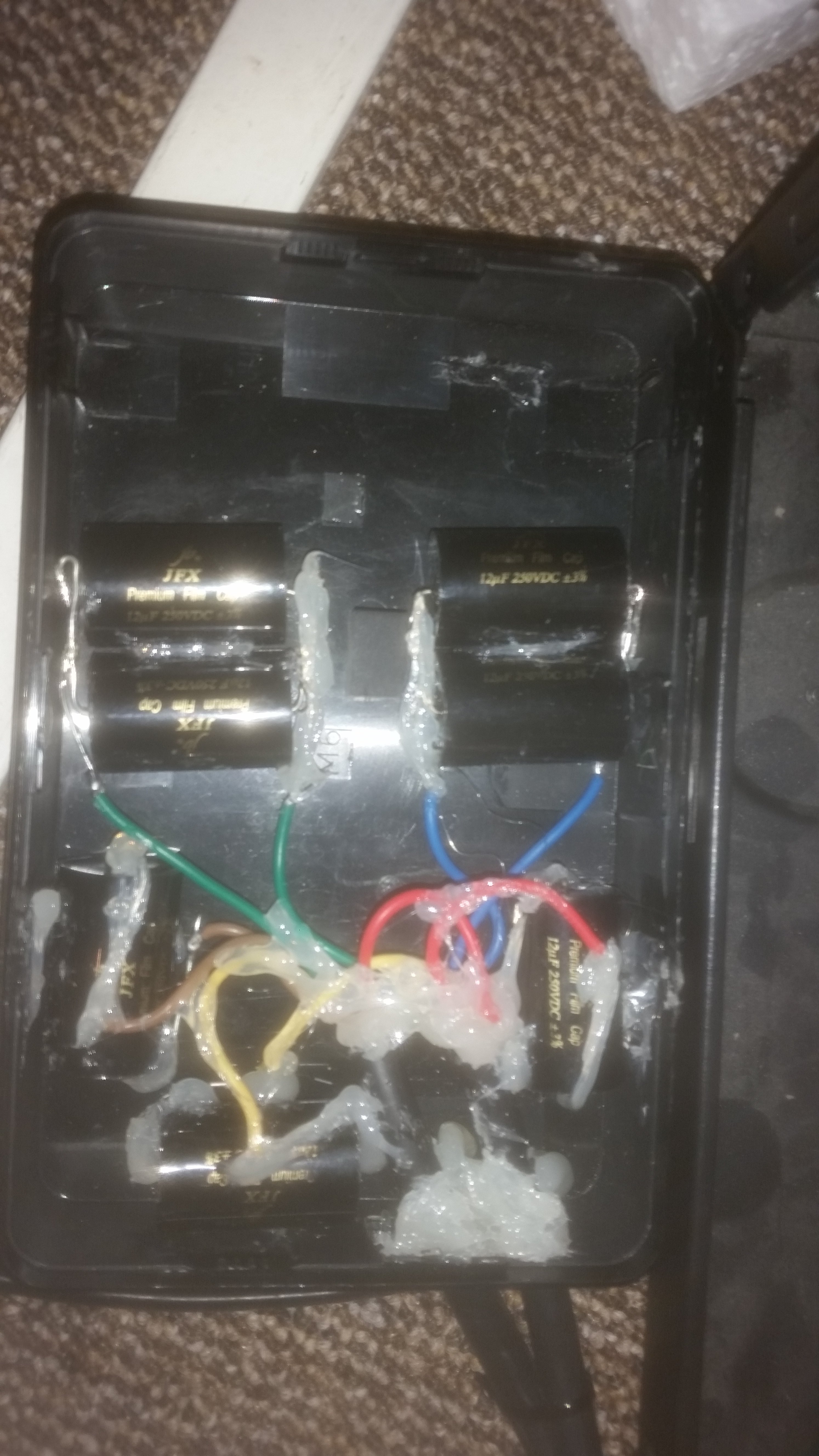
3) Now comes the tricky part that can be modified based on your PC and the capacitors you bought.  This is the arrangement I went with.  You can see the use of shrink wrap and hot glue.  I had to use the solid core copper wire to bridge the distance between back of the capacitor and solder point.  I'm sure I will make this more detailed as questions come in.


Each capacitor is hot glued on the connection end where they are joined (on the doubles) and also underneath to secure them to the board
 
 
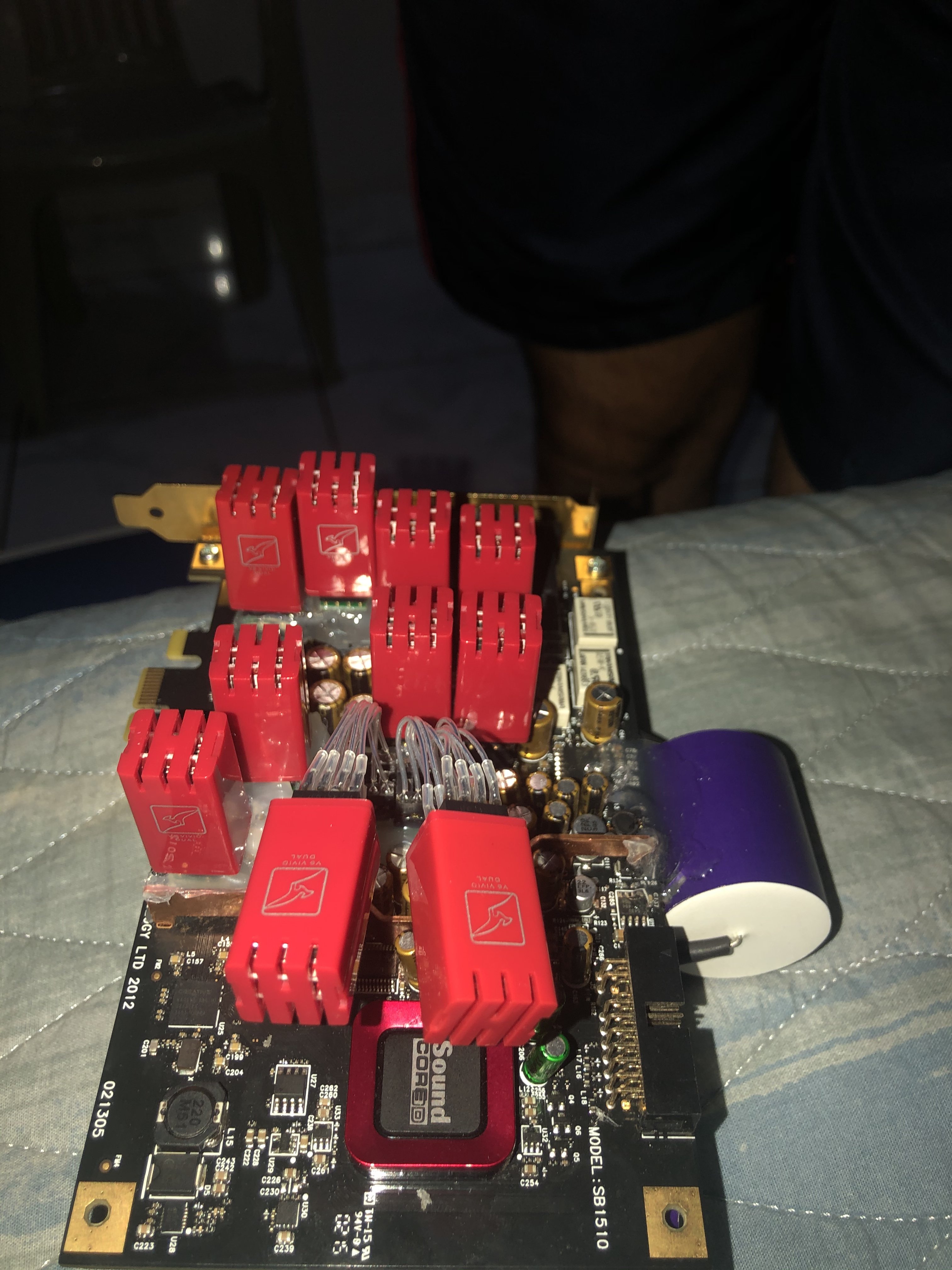
You can see in the next picture the type of spacing I have using the Thermaltake Water2.0 Pro and if you have some of the big air coolers, you should have close to the same since my tubes coming out are at the same spot a heat sink would be normally.
 
 
(please excuse dust in next picture)


Any questions, feel free to ask.
 
Mar 11, 2014 at 9:46 PM Post #27 of 272
Good job. How does it sound to you??
 
Mar 11, 2014 at 10:45 PM Post #28 of 272
I only had about 30 minutes before I had to switch over to my Aune T1 (noise issues where I live), so I can't really make a judgement yet.  The one thing I did notice right off the bat was a much more pronounced mid range.
 
 
BTW here is what my opamp setup looks like (see sig for details) before I put the caps on the back and made it difficult to remove the cover, since I never took a picture after swapping out my MUSES 01


Mar 12, 2014 at 1:09 PM Post #29 of 272
Yes more pronounced midrange & treble is indeed a characteristic of the modification, however a frequency sweep will not reveal any of that type of change. In fact you will see flatter response at the bottom end due To The direct coupling Of the I/V to buffer amp stage. It is like it is fleshing out the harmonic structure of the music better than before the modification.
 
Mar 13, 2014 at 8:14 AM Post #30 of 272
I've got about 5 hours on it now and after adjusting my EQ curve there is clarity there that didn't exist before. BTW, if you want to use any of my pics in your OP to show users what it looks like, that is fine.
 

Users who are viewing this thread

Back
Top