
robrob
100+ Head-Fier
- Joined
- Jul 10, 2013
- Posts
- 473
- Likes
- 150
I know many of you are like me and want to better understand how tube amplifiers work. I have created an easy to understand web page that details how every component in a tube amplifier works including how the rectifier, preamp and power tubes work. There's no math and I use a lot of graphics to keep it interesting. The amp I use as an example is a monophonic guitar amp but everything still applies to audio amps.
I've been getting good feedback on the page and wanted to offer it up to curious audiophiles. There's no advertising and I get no compensation for its use.
How Tube Amplifiers Work
Here's some sample content:
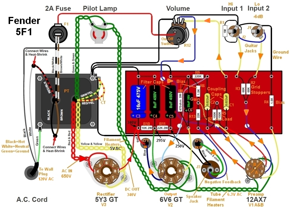
This shows the signal flow through a simple but elegant Fender Champ guitar amp. Signal enters at the guitar jacks at upper right. Orange arrows show the signal flow that ends at the 6V6GT power tube and output transformer at bottom center (the original image on my webpage is larger and easier to read).

Here's the same guitar's schematic. The above layout diagram has matching component numbers so you can easily go between the layout and schematic. Again signal flow is shown by orange arrows.

If you want to know how amplifiers work please check it out. It's a pretty good overview of audio electronics and amplification. As always I'm open to suggestions and corrections.
This is an email I just received from a website visitor:
Rob Robinette
I've been getting good feedback on the page and wanted to offer it up to curious audiophiles. There's no advertising and I get no compensation for its use.
How Tube Amplifiers Work
Here's some sample content:
This shows the signal flow through a simple but elegant Fender Champ guitar amp. Signal enters at the guitar jacks at upper right. Orange arrows show the signal flow that ends at the 6V6GT power tube and output transformer at bottom center (the original image on my webpage is larger and easier to read).
Here's the same guitar's schematic. The above layout diagram has matching component numbers so you can easily go between the layout and schematic. Again signal flow is shown by orange arrows.
If you want to know how amplifiers work please check it out. It's a pretty good overview of audio electronics and amplification. As always I'm open to suggestions and corrections.
This is an email I just received from a website visitor:
Code:Rob - A salute to you for your fine website! I am a "Fiber Optic Technician/Electrician by trade. Yours is the first, (AFTER MANY ATTEMPTS) to supply "tube schematics" understandable to a novice. Although I understand fiber optic "cutsheets", (very complex) I could never understand tube schematics as they are not "precise", conveluded and do not spell out "exactly" how a circuit ties together when compared to a fiber optic/telecom blueprint. My eyes have been opened! Too bad you could not make your pictures/schematics available to the mass public who are audiophiles like myself. Just a note to say how thankful I am! I now feel like I can build anything I want to build. Within 2 hours of stumbling across your info, I was able to troubleshoot a Bogen CHA 20 and a McGohan 506, (with EL34's) and get them up and running perfeclty! Many Many Thanks! Lord Bless, Jeff
Rob Robinette

