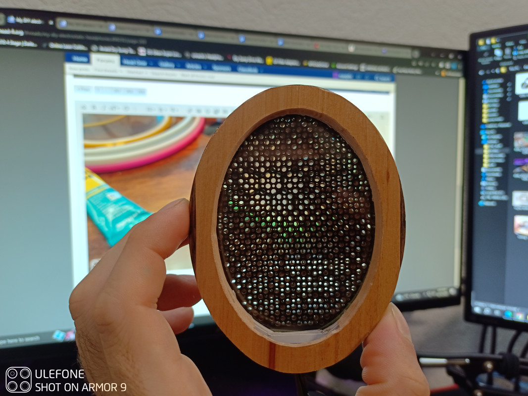
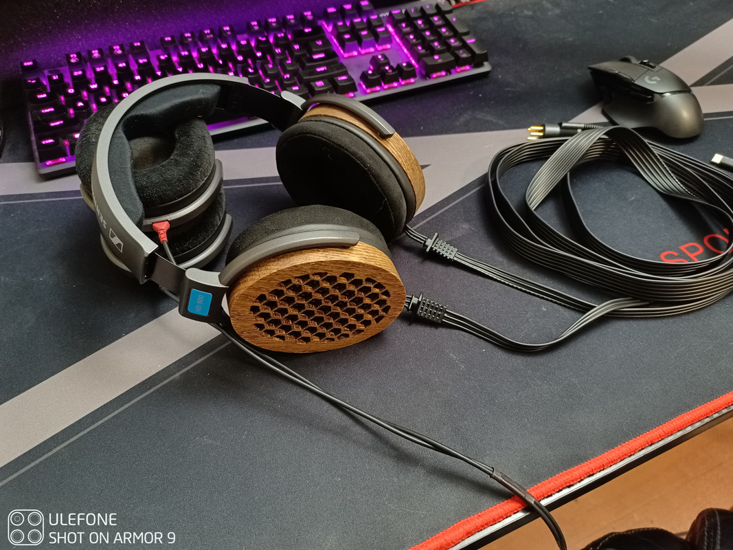
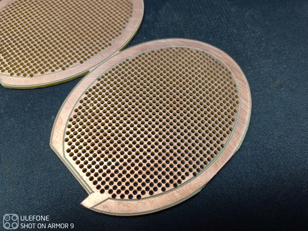
Howdy y'all! I'm Max, and I am new to the world of audio. Started watching Crinacle on YouTube and it was downhill from there. Anyways, I somehow found my way here and like most was inspired to try my luck as well. I made a pair of HD600 knockoffs (with borrowed parts, seen below). In essence they are FR4 .5mm PCB spacers and 2mm stators. Active diaphragm area of 90x66mm with 3um Mylar. Air gap of .5mm. Stators have both 2mm and 1mm holes drilled, ended up using and engraver to isolate only the inner perforated area to increase sensitivity as they ended up very quiet originally. I was a little greedy trying to maximize the diaphragm area and suffered immensely gluing the Mylar to the spacers as they are only 5mm wide... area for wires to fit into were also overlooked... but ill say this was a successful "functioning" prototype.
Regretting lack of space
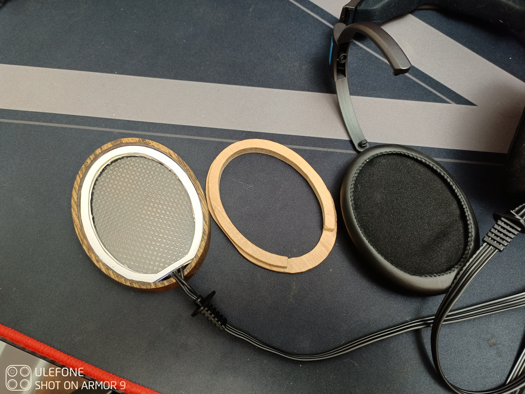
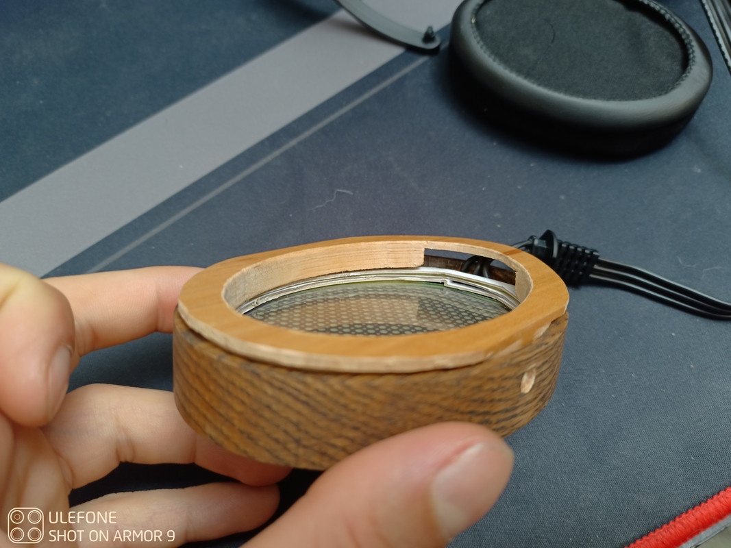
used a piece of scrap wood to compress the driver and hold the awesome earpads from Brainwavz. They just have a slight interference fit and due to woodgrain stay together quite nicely. And yes those are cardboard spacers you see in there. Messed up on the depth the compression ring. That's what CAD(cardboard aided design) is for right? Its all on the user side of the dust screen so all should be well, and temporary.
I used a Stax L500 cord as I didn't feel savvy enough to fabricate my own.
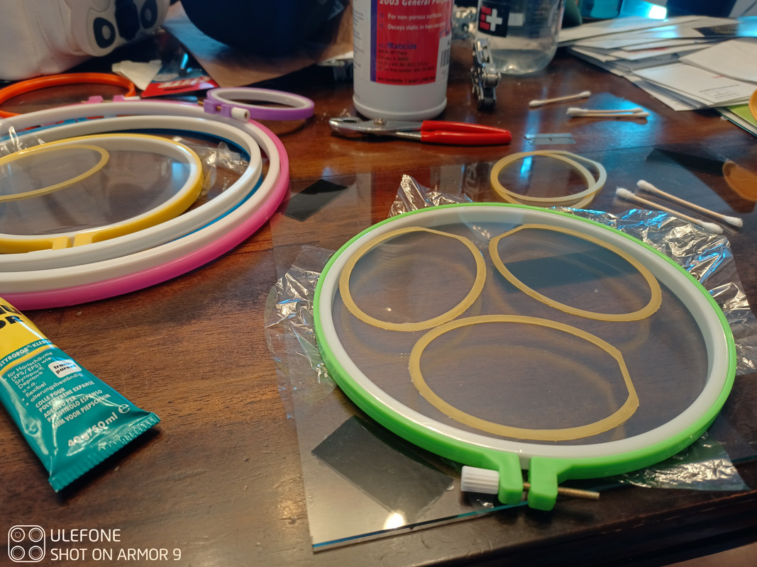
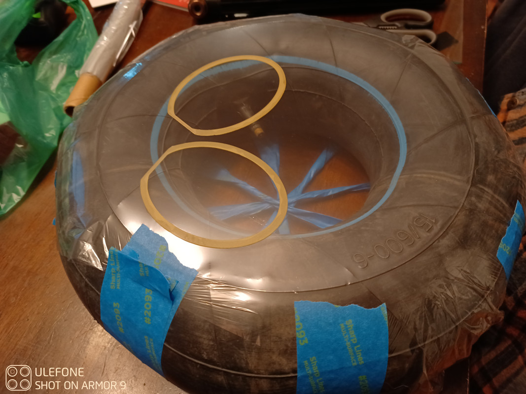
I saw someone here using and embroidery ring for a Mylar tensioner and gave that a shot. If interested in this method, avoid the temptation to cheap out on the rings. I could only just keep the wrinkles out by slowly and gently pulling the excess material on the outside of the ring. Any attempt at stretching would result in the excess material on the outside to tear then I would loose all tension in the ring. I will be looking into other methods. Glue used was UHU POR.
I attempted to make some crumpled dust screen but they ended up sounding like plastic bags crinkling in my ear as I did not tension them enough. Further experimentation required. For the coating material, I used Staticide 2003:
https://www.amazon.com/dp/B004TMTNBC?ref=ppx_yo2ov_dt_b_product_details&th=1. I cannot speak for longevity as they have only been together for 3 days as of this post but I will update.
Now onto how they sound. As I have only the HD600's to compare to. I can confidently say these are my new favorite. They still need a lot work (and their own headband) to be considered complete but I'm absolutely blown away by the clarity, sound stage, and bass these things throw out. Even at higher Db, I can barely make out any distortion. Consider me hooked! I can see why people get spend-y with this driver type. But as a budget prohibited person, the DIY scene is my jam. This was a very enjoyable project and I am grateful to everyone here who went through much trial and error and sharing their results to better the community. I would love to be part of that as well, so I will try to chime in as much as I can. Cheers! - Max